Success! At long last I am thrilled to report that my DEC H750 power supply is fully operational. All the voltages check out, and both with and without load the waveforms show no ripple. It didn’t come easily, of course, but I got really lucky and along the way I learned a lot about DEC’s power supplies.
What follows is a bit long. Unless you’re really interested in reading too much information about the process, please feel free to skip it and just say “Oh, that’s nice, Seth got his power supply working. Jolly good!”
In The Beginning…
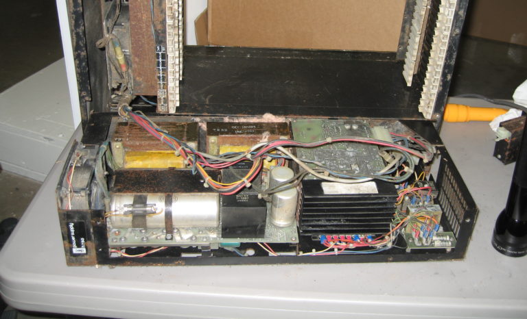
If you’ll recall, when I first pulled the power supply to inspect it I was horrified by what I found. The whole thing was dirty, filled with fiberglass insulation that mice had stuffed into it to make nests, and the chassis was badly rusted. I despaired of ever making it work again. The first challenge, then, was just cleaning it out.

The bulk of that stuff was taken care of with a vacuum cleaner and some brushes. Once the bulk of the nastiness was cleaned away, I got down to business of inspecting it for obvious signs of failure. The H744 (+5V switching regulator) in my power supply was the most badly hit part, it was literally caked in mouse droppings and rust. Rather than try to clean it or repair it, I decided to poke around and see if I could find a new one on eBay. You never know, right? Well, unbelievably there was one available! Not only that, it was actually a very reasonably priced Buy-It-Now auction, a “normal person” price instead of those over-inflated DEC reseller prices. So naturally I jumped on it, and a few days later I had a very clean, very working H744 to replace the mouse-ruined one.
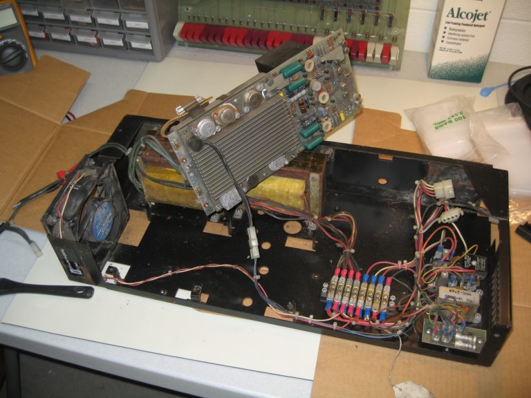
The other regulator board was just a little dirty but otherwise looked in reasonably good shape, so I decided to just replace all the rusty screws, clean it up, and try to use it. Incidentally, for doing deep cleaning on the electronics I’m using a new (to me) detergent made by Alconox. It came highly recommended by a friend who used to work at DEC and who has used it for restorations himself, and I have to say it works amazingly well. It’s perfectly safe, but very good at removing organic compounds from glass, metal, and plastic. In other words, it was practically made for this job. All I had to do was soak the regulator board in the Alconox solution for a couple of minutes, agitate it a little, then rinse it and thoroughly dry it. It came out looking almost new.
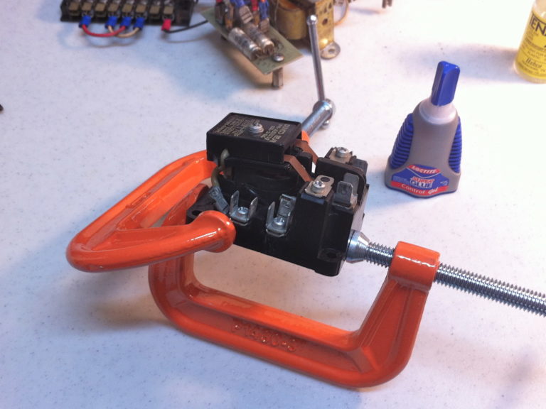
There were a few other parts to look at, of course. The hardest hit of these was the cooling fan, which was a total write-off. I also had to do a little surgery on the power relay, which had a cracked plastic base. But apart from this, there just wasn’t anything else that looked like it wouldn’t work. Very good news indeed!

Powering It Up
With all that cleaning and inspection out of the way, I crossed my fingers and plugged the H750 into my Variac, set it to about 50V, and turned it on. No sparks. Good!
The H750 main power is controlled by a relay, and the relay is triggered by closing the key lock on the front panel of the 11/35. Since I was testing the H750 in isolation, I just rigged up a switch and connected it to the relay. I increased the voltage slightly and flipped the switch. CLICK! The relay snapped closed and the two big transformers started humming. Nothing exploded. I took this as a good sign. I gradually incrased the voltage on my Variac until it hit 115V. Everything continued not to explode. Fantastic!
At that point I started to take voltatge readings. There are four outputs from the power supply: two +5V, one +15V, and one -15V. Well, I was getting one +5 and the -15V alright, but the other +5V and the +15V reading were nowhere to be found.
Damn. OK, time to do some debugging.
Naturally the first thing I wanted to find were schematics for the power supply, but there were none to be found in the usual online places, so I had to do some extra deduction and sleuthing.
In the H750, the primary +5V supply comes from an H744 regulator brick, while the secondary +5V, +15V, and -15V supply all come from a separate board. The two missing voltages were supplied by this regulator board. The board in question has only two identifying bits of text on it: one is the name, “REGULATOR BOARD”, and the other is a part number, “5409728”. Combining these two in Google yielded hits right away, but interestingly none were for the H750. As I soon learned, the 54-09728-00 Regulator Board was used in a number of DEC power supplies for all kinds of products. The one I found the most information on was the TM03 tape drive. A little further Googling found not only the full engineering drawings for the TM03, but also a full maintenance manual for the TM03’s power supply, the H740. Bingo! Close enough!
(The H740, it turns out, was used in a bunch of DEC stuff, including the PDP-8/m and PDP-8/f. But that’s another story…)
Debugging

Now armed with the full manuals for the regulator, I set about debugging. It was pretty clear from the get-go that -15V was absolutely fine, but that +5V and +15V were completely dead. No matter how far I traced them back into the circuit, I was getting nothing. I made it all the way back to the bridge rectifier, and STILL got nothing. The filter cap wasn’t even getting charged!
And that’s when I read the “H740 Troubleshooting Chart” for about the sixth or seventh time and realized the answer had been staring at me in the face the whole time. Right there, under the very first suggestion for “No +5V and +15V Output”, it says:
“D14 or transformer opened”.
Oh yeah. Duh. D14 is the bridge rectifier. I had just assumed it was fine and hadn’t bothered checking it. Feeling rather stupid and embarrassed, I desoldered D14, dropped in a replacement (I actually had one on hand! Hooray junk box!), and fired it up again.
Yyyuuuuup. It worked perfectly. I could have saved myself probably 3 or 4 hours of debugging if I’d actually bothered to take the troubleshooting chart to heart the first time.
So there it is. After a couple of days of solid work, I have a fully working power supply. Onward and upward, as they say.
Comments