I’ve been delving more into the wire protocol the VT100 keyboard uses to talk to the terminal. As you may recall from my first post in the series, communication is bidirectional, asynchronous serial over a single wire. The protocol uses three reference voltage levels (0, 6, and 12 volts) and makes each end sample its own output to see who’s talking, which is… well, it seems weird to me, but I’m sure they had a good reason. So that leaves the actual signaling. How did they send the clock and data using those levels?
Well, it turns out that they used PWM (pulse width modulation). Each bit sent across the wire is encoded on top of 16 clock cycles. The exact number 16 is dictated by the UARTs the designers chose, the Western Digital TR1865. The TR1865 expects a square wave clock signal, and samples its serial input on the falling edge of the pulse for sixteen clock cycles per bit. The DEC engineers cleverly decided to use PWM to change the duty cycle of the clock wave form between 25% and 75%, and feed the same signal to the clock input and serial input of the UART. The serial data can then be separated from the clock signal with a very simple RC circuit and a comparator.
From the Technical Manual, (pp. 4-37 – 4-38):
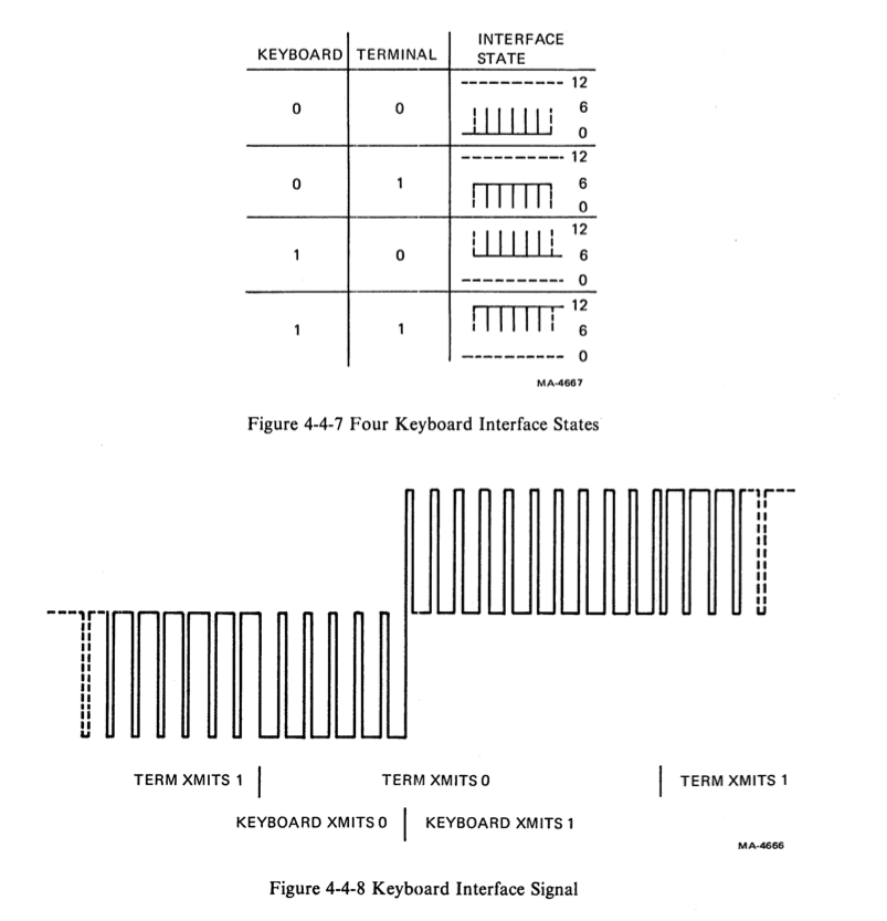
The keyboard requires a clock for its operation and is provided with one by the terminal controller side of the interface. To transmit a clock independently of data on the same wire, the terminal side of the interface generates a clock signal within which data is encoded as a pulse width modulation. The terminal circuit produces a 75 percent high pulse width output for the mark state. Data transmission causes the clock output to switch between 75 and 25 percent pulse width (duty cycle). […] The negative transition of each output pulse occurs at the clock interval regardless of the presence of data. This transition is therefore the reference point for the keyboard clock at the receiving end.
[…]
The keyboard recovers the modulated clock signal sent by the terminal but must also separate the data from the clock. […] Data is extracted from the combined clock-data by a simple resistor-capacitor filter on one input to a comparator. The other comparator input is referred to one-half the power supply. Because the duty cycle of incoming data is either 1/4 or 3/4, the capacitor charges to that proportion of the supply voltage over the 16 clock periods of each bit. The comparator switches when the capacitor voltage rises or falls past the reference value.
So, the combination of the duty cycle and line voltage give the complete set of four states, as shown in the following two figures. I am truly amazed.
Keyboard Status
There’s something else I consider odd, too. The keyboard has six status LEDs and a speaker in it. The speaker is used for beeps and keyclicks, the LEDs show various status bits. All this state is controlled by the terminal, not the keyboard. In fact, the keyboard doesn’t even latch the status data outside of the UART. Instead, the status is sent by the terminal to the keyboard every 1.28 ms (!!!!). The UART in the keyboard receives this data, puts it out on the 8-bit parallel UART output, and drives the LEDs and speaker directly through a pair of SN7406 drivers. Think of it as DRAM vs. SRAM, if it helps; the state is constantly being refreshed.
That means that my VT100 to USB translator is going to have to do the same thing. It’s going to be a pretty busy little box.
EDIT: An earlier version of this post said the keyboard status was updated every 7.945 µs. This is incorrect. 7.945 µs is the period of the clock signal, not the keyboard status update refresh.
Comments