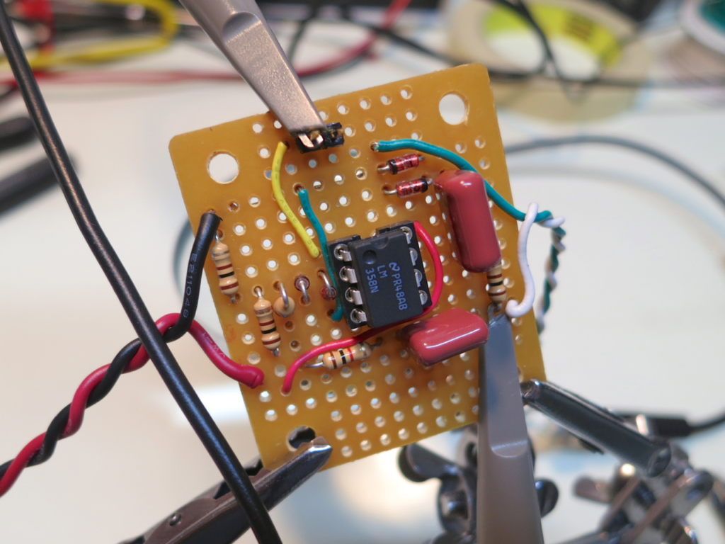
I put together the cassette input circuit tonight on a teeny-tiny little perfboard. It’s not really much to look at, but happily, it works!

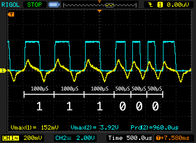
Its sole purpose in life is to take the audio from a cassette and turning it into a useful digital signal. Here’s a capture from my scope, showing the cassette input on the yellow trace, and the digital output on the blue trace. The input is showing 200mV per division, so it’s a peak-to-peak of about 300mV. The output trace is showing 2V per division and it’s peaking at about 3.9V, but that’s because I forgot a pull-up resistor. I’ll add that tomorrow!

I’ve annotated the screenshot to show how the data is encoded on the tape. This is actually from a copy of APPLE 1 INTEGER BASIC (the original, the one that Woz wrote!) that I downloaded as a digital audio file from Brutal Deluxe Software and then recorded to cassette myself. The Apple II used the same format. A “0” is encoded as one cycle of a 2 kHz signal (about 500µs wide), and a “1” is encoded as one cycle of a 1 kHz signal (about 1000µs wide). This seems like a fine format to use for my own project, so that’s what I’ll do.
I have a few minor tweaks to do to the hardware before I mount it into the project box next to my 6502 SBC, but I should have all the hardware done tomorrow. Then it’s onto the hard part: the software.
Comments