The other night I went to bed frustrated with AVR programming. I was trying to come up with some perfect scheme that would allow me to generate PWM “the right way” so I wouldn’t have to bit-bang, but it was janky at best. I wanted to use interrupts to drive the keyboard decoding, but there was no guarantee they’d get serviced in time. Then I looked into whether I could somehow hijack the AVR’s USART to work with an external clock and still do 16-sample encoding/decoding (you can’t). It was hard, and I could sense that I was setting myself up for a terrible month of debugging impossible timing issues.
And then it hit me. What if instead of all this software, I do it the old fashioned way? What if I use hardware?
OK, so I know the UART that DEC used, the Western Digital TR1865, is no longer produced and it’s very hard to find. But it turns out there’s an equivalent part made by Intersil! The pin compatible and software compatible HD-6402 UART is not only still made, my favorite local parts shop Anchor Electronics has them in stock. Eureka!
Goodbye, Plan A. Hello, Plan B!
With a compatible UART, I can handle all of my timing in silicon. The UART can feed 8 bits of parallel data to the Teensy 2.0, and the microcontroller can in turn feed parallel data back to the UART. The software will become a much easier problem to solve.
Here’s the circuit I designed mostly stole from DEC.
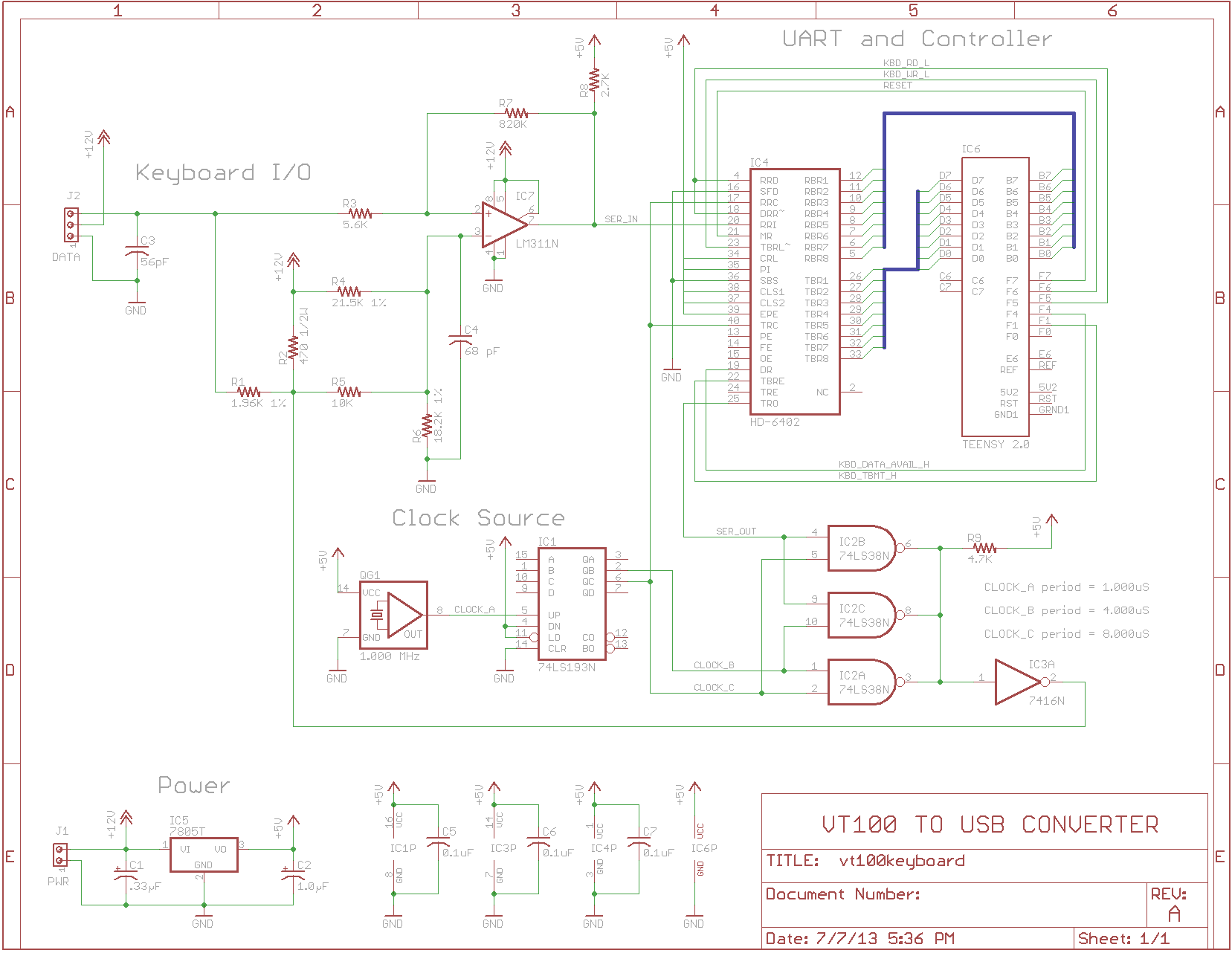
The clock source is a 1 MHz crystal oscillator with TTL-level output. It feeds into a 74LS193, which is the only thing I had on hand that makes a reasonable clock divider (yes, there are much better choices out there, but it’s the best that I had in my junk box). The 1 MHz input frequency was chosen because the VT100 keyboard and the circuit in the real VT100 both expect a clock with an average period of 7.945 uS. A 1 MHz clock is easily divided by 8 to produce a clock with a period of 8.000 uS, which deviates from the “ideal” by less than 0.7%. The only thing that it should affect is the RC filter that separates the data from the clock, and I would be absolutely shocked if that 0.7% made any difference at all. It’s probably well within the margin of error.
The rest of the circuit is straight from the VT100 schematics. The resistor and capacitor values are exactly the same. The RC filter should behave the same. The PWM-generating circuit composed of the two clock sources, the serial data source and the 74LS38 should behave the same.
The Teensy 2.0 will either use interrupts or poll the KBD_DATA_AVAIL_H
and KBD_TBMT_H lines to see when data is available to read, and when
it’s OK to write a status byte. It should have plenty of time to talk to
the USB host with so little work to do.
I’m going to breadboard this up right away and see how far I get. If it looks like a viable solution, I’ll solder up a proto board and start writing software.
Comments