I know I said I was going to take a few days off, but I couldn’t help myself. I spent about two hours looking at signals on the PDP-11/35 today.
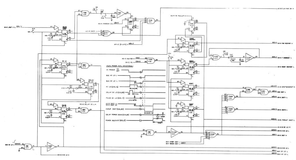
I have decided to focus on the POWERUP INIT L signal. This line is normally high, but is supposed to go low for 20ms at system power-on time as soon as the BUS DC LO line goes high. For reference, here’s the complete schematics for both power-off and power-on sequence bus delays.
The chip responsible for POWERUP INIT L is a 74123 in position E26. After my experimentation last weekend I thought it was bad, so I got some replacement parts, pulled the 74123 and replaced it. But much to my chagrin, very little has changed. Here’s a typical startup sequence as it is now.
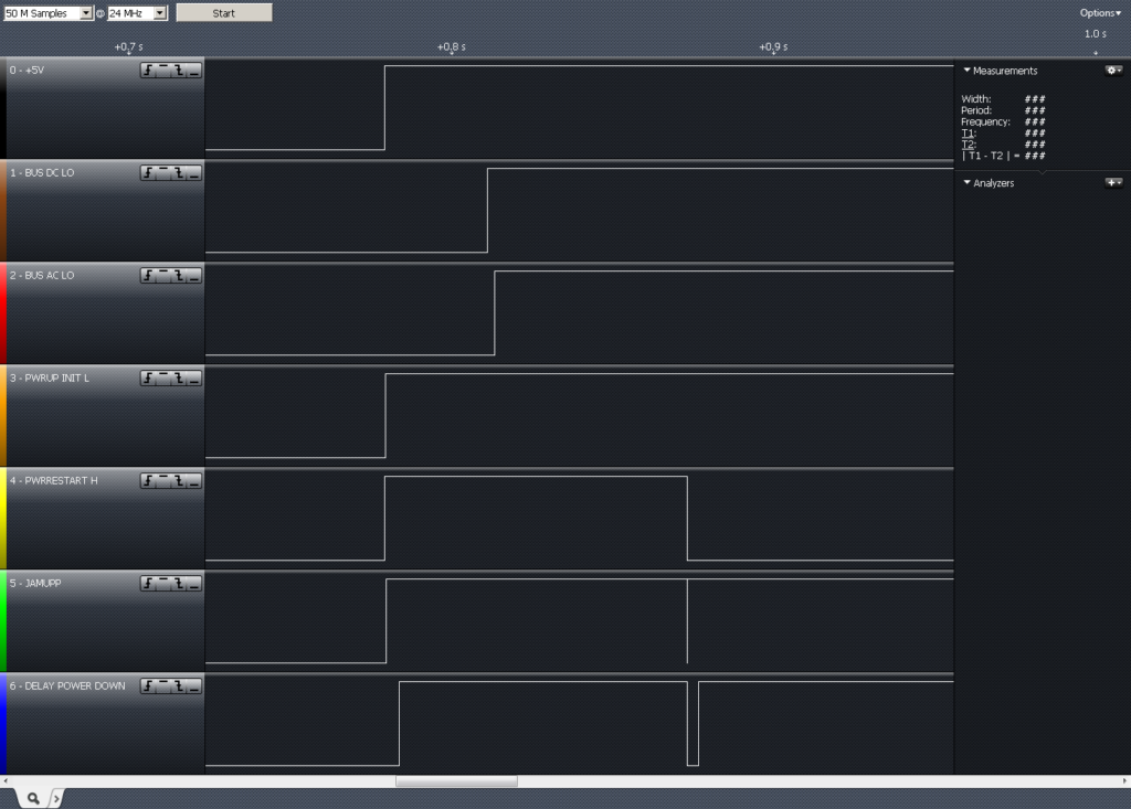
At least the crazy 50ns glitch is gone, but the output still isn’t going low. Well, not usually, anyway, and that’s what’s even weirder—I actually have seen it go low for ~20ms on several occasions, but only two or three times out of dozens of power-ups!
I’ve spent a lot of time puzzling over this part. Take a look at the schematics around the PWRUP INIT 74123. I’ve called it out here for a better view.
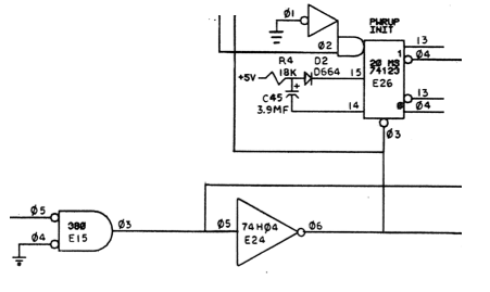
The inputs could not be simpler. Pin 1 is the A input, it’s tied directly to ground. Pin 2 is the B input, and it’s pulled up to +5V through a 1K resistor. Pins 15 and 14 are the RC network used to set the pulse width. Pin 4 is the PWRUP INIT L output, the one that’s supposed to pulse low for 20ms, but doesn’t (usually). And finally, pin 3 is the BUS DC LO input. It goes from LOW to HIGH when the power supply signals that it is ready.
Now, I’ve replaced the 74123, in fact I’ve tried no less than four different 74123 ICs and two 74LS123 ICs. I’ve pulled and carefully checked C45, and verified it’s within 5% of 3.9µF. I’ve checked the resistance across R4 and verified it to be 18K?. I’ve checked D2 with the diode test setting of my multimeter, and it’s fine. I watched the BUS DC LO input both with my logic analyzer AND with my oscilloscope, and verified that it goes high when it’s supposed to go high. So to say I am puzzled would be an understatement.
The nearest I can come to a theory right now involves what I’ve observed around that circuit when I apply power. Check this out.
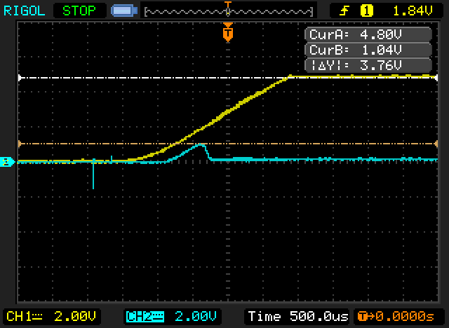
The yellow trace is pin 2, the one that’s pulled +5V through a 1K resistor. (Incidentally, don’t be alarmed by the slow rise time. That’s within specs. According to the maintenance manual, the DC regulator has a maximum +5V output rise time of 30ms under full load, so this rise time of < 3ms is absolutely fine.)
But then check out the CLR input, on pin 3. That little bump is 1.04V! It’s higher than the maximum LOW input voltage of 0.8V. Of course it’s also lower than the minimum HIGH input voltage, so it should not be triggering anything, but maybe it is? I know the 74123 is considered a real pain in the butt to work with because of how noise sensitive it is, but I’ve never used them before, I have no practical experience here.
I also wanted to figure out WHY that little bump is making it to pin 3. So here is another waveforms that I found very interesting.
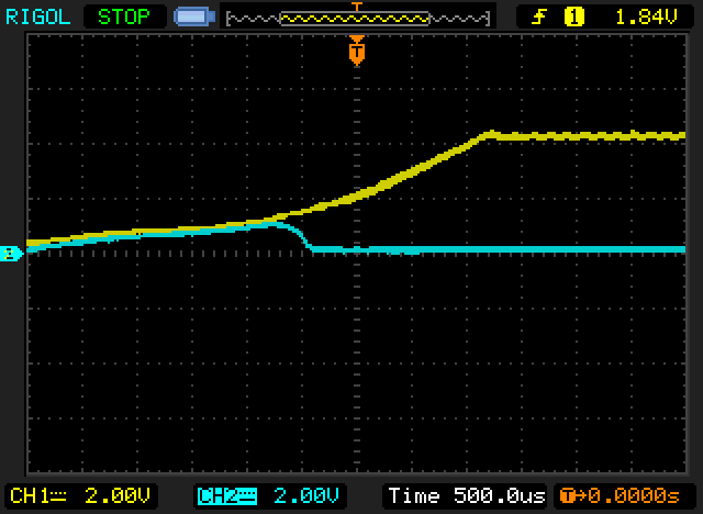
What we’re seeing here is an inverter on a 74H04 at power-on. The yellow trace is the input, and the blue trace is the output. The output is being fed directly into pin 3 of the 74123, and you can see that the little blue hump is there, as expected. Note that the very slow rise time on the input is at initial power-on, so that’s not a logic signal, that’s just the input drifting high as DC starts to flow in from the power supply. But apparently the damn thing actually starts to try to invert the low input signal, thus generating that little output hump.
So to boil it all down, this is my condensed working theory
- The inverter (74H04 E24) is (possibly incorrectly?) trying to invert what looks like a LOW input, but it only lasts a few ms before the input is over the 0.8V TTL input threshold and the output goes low again.
- The small 1.04V generated by the inverter is just enough to put the one-shot (74123 E26) into an undefined state, so it doesn’t trigger later on when it’s supposed to. But it’s VERY close to the 0.8V TTL threshold, so very occasionally it winds up in a good state, and does trigger when it’s supposed to.
Maybe I’m grasping at straws. But anyway, now my question is what to do about it? Could a marginal 74H04 IC be the cause of the little hump? Is there anything else I should look at around here that I’m just missing or overlooking?
Comments