Now that the power supply is straightened out (at last!), I’ve been able to start tracing logic and seeing what’s up with the CPU.
First things first: It still doesn’t run. Last week before the power supply died I mentioned that I thought it may have been due to low voltage. That was wishful thinking. Now that the voltage levels are good, the behavior of the CPU is roughly the same. It is time to go spelunking into the lair of the beast.
I wanted to tackle the HALT/ENABLE switch first. If the CPU is halted (switch set into the HALT position) it should be running the console loop, waiting for commands from the console switches, but I have no evidence that it is. I had already verified that the 7410’s on the console were working correctly, so my investigation took me from there to the CPU itself.
Thanks to countless people around the world, a lot of DEC’s documentation lives on in scanned form, including the KD11-A Maintenance Manual and Engineering Drawings. These have proven absolutely essential. It didn’t take me long to trace where the HALT switch feeds into the CPU. It turns out it has several destinations: On the M7235 STATUS module it feeds into a 74H11 AND gate, and on the M7234 TIMING module it feeds into a 7474 flip-flop, a NOR on a 7402, an inverter on a 7404, and a NAND on a 7400.
I took a breadth-first approach to tracing the HALT signal by looking at the inputs and outputs on each of these gates. I was able to watch the signal go from HIGH to LOW and back again as I flipped the switch, so I knew the switch, the cable, and the backplane connections it used were good. Everything looked OK until I go to the 7404 inverter on the TIMING module.
Bingo! My first incontrovertibly bad part! It didn’t take me long to replace the 7404. One very tiny problem down, who knows how many to go.
I hit kind of a dead end on tracing the HALT switch, because most of the other gates have other inputs that weren’t changing. After my little 7404 victory, I decided to start looking more closely at the timing situation. How did I know what was going on at startup? Could I figure out whether I even had a clock? Was any microcode running?
I figured I should start by watching what happens at power-up. There’s a nice little diagram in the maintenance manual, page 3-11, that shows the expected timing of various signals after the CPU is turned on, so I decided to watch these lines on a logic analyzer and see what I got.
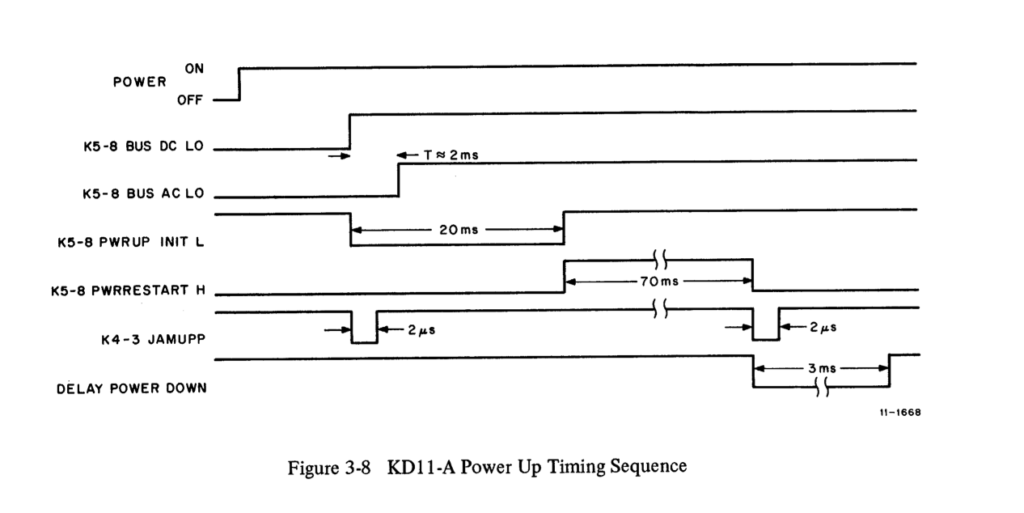
I probed the following lines and IC locations on the M7235:
- +5V DC
- BUS DC LO (DEC8881 E16, 04)
- BUS AC LO (DEC380 E15, 10)
- PWRUP INIT L (74123 E26, 04)
- PWRRESTART H (74123 E25, 13)
- JAMUPP (7474 E44, 03)
- DELAY POWER DOWN (74123 E34, 12)
Well, I got a mostly correct waveform on my PDP-11/35’s startup:
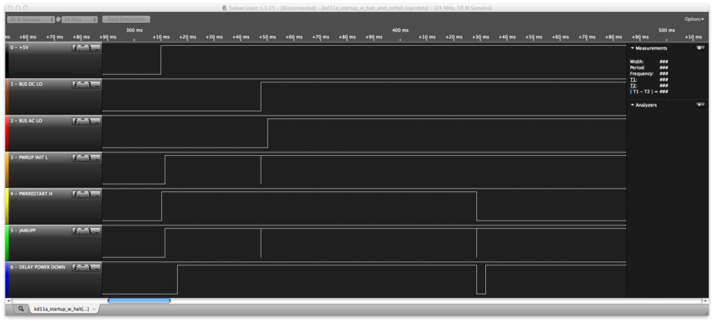
+5V shows where I turned on the system. About 40ms later, DC LO goes high, then AC LO goes high a few ms after that. They seem to be behaving exactly as they should.
The little spikes there on the JAMUPP line are also correct - in reality those are about 3µs wide, exactly as they should be [EDIT: actually, plus or minus a microsecond - I need to investigate that. microseconds matter!]
DELAY POWER DOWN looks good too. The line is pulled low for about 3ms just as PWRRESTART H and JAMUPP both go low.
But PWRUP INIT L is seriously wrong. What looks like a little spike is a couple of < 1µs blips. That line is SUPPOSED to go low right after BUS DC LO goes low, and stay low for 20ms. That’s part of the function of the 74123 IC, it uses an RC network as a timer—in this case an 18K resistor and a 3.9µF capacitor. Different values would be used for different delays.
My first thought was to double-check that noise and see what it looks like on an oscilloscope:
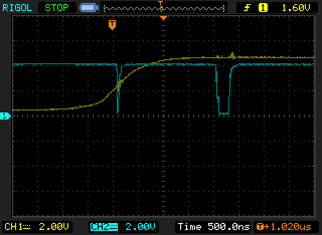
The yellow trace is DC LOW going high, and the blue trace is PWRUP INIT L. As you can see, that really is a very tiny blip. It tries to go low and fails miserably.
I immediately tested the capacitor and resistor in the RC network, but both are totally fine. It’s a tantalum cap anyway, so I wouldn’t really expect it to have gone bad. That pretty much means by process of elimination that the 74123 is bad. No surprise, actually, because the legs are pretty badly spotted with rust.
So that’s where I sit as of tonight. I obviously have startup timing problems, and so far two bad ICs. I’ve ordered a little care package of some 74LSXX, 74ALSXX, and 74FXX parts from Jameco, so they should be here by Wednesday at the latest. Some 74LS123s are among them. I’ll replace E26 and see if the startup waveform improves. There’s also a mystery with PWRRESTART H going high too soon, but I suspect that’s because of the glitch in PWRUP INIT L. We’ll see.
I think this is going to be a pretty slow process. But I’ll make it work yet!
Comments